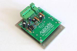
When motor slows down moving machine mass, the motor will act as a generator. Regenerative currents are rectified by motor drive and the energy returns to the main DC rail. As the capacitors on the DC rail charge, the voltage rises.
The motor brake circuit allows excess power to be dissipated if the DC power rail exceeds a specified limit.
In cases of large moving mass and rapid deceleration, increasing the voltage of motor drive power supply can lead to permanent damage of motor drive.
Motor break circuit MB-2 follows amplitude of input AC voltage and output DC voltage of rectifier for motor drive power supply. If voltage generated by motor increases more than 5V compared to amplitude of input AC voltage, brake circuit will activate. In that way, it prevents uncontrolled increasing of power supply voltage. LED indicator built in motor brake circuit MB-2 shows when the brake circuit is active.
Motor brake circuit also quickly discharge electrolytic capacitors in the power adapter after powering off.
Motor brake has built-in circuit for power supply of control electronics of the motor brake circuit MB-2.
The braking resistor is externally connected to the motor brake circuit MB-2 via terminals. There is also the option of installing braking resistors to the motor brake circuit MB-2.
Photo gallery
https://www.audiohms.com/en/cnc-electronics-products/pmdc-servo-motor-drives-and-accessories/motor-brake-circuit-mb-2#sigProId020ea019fe
SPECIFICATIONS
| Characteristics | Description - Value |
| Description | Motor brake circuit with floating voltage brake activation |
| Power supply | Um = 50 ÷ 210VDC |
| Maximum brake current | 15A |
| Brake voltage activation | Um + 5VDC |
| Breaking mode | Via additional braking resistor (external or optionally on motor break circuit MB-2) |
| Dimensions (W x L x H) | 102mm x 77mm x 30mm |
| Weight | ~150g |
NOTE: specifications are subject to change without notice


